How to Improve CNC Machining Precision?

Improving CNC machining precision begins with understanding that accuracy is a process, not a final inspection result. Professor Yusuf Altintas, a leading authority in machining dynamics, states, “Machining accuracy depends on understanding the process, not simply measuring the final part.” This principle guides every reliable precision strategy.

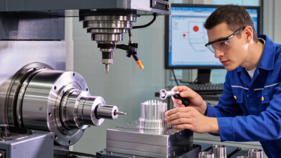
CNC machining precision can change within a single production shift. A spindle may warm by several degrees. A cutting tool may develop 0.02 millimeters of wear. Even a small amount of runout can alter a bore diameter. Skilled machinists therefore check tool offsets, fixture stability, coolant temperature, and machine alignment before cutting critical features. They also use probing cycles and calibrated gauges to compare actual dimensions with the CAD model.

Small details matter.

However, no machining system remains perfectly stable. Thermal growth, vibration, material stress, and operator judgment can still create variation. That reality deserves attention. A process that performs well on aluminum may behave differently with stainless steel or titanium. One universal solution rarely works. Engineers should record cutting speed, feed rate, tool life, and measurement results after each trial. This evidence reveals patterns that intuition can miss.

The following guide explores practical ways to improve CNC machining precision, from machine calibration and workholding to tool selection and environmental control. It also considers a common weakness: measuring too late. Precision improves when manufacturers control the causes of variation before the finished part reaches inspection. That requires patience, disciplined documentation, and a willingness to question settings that appear acceptable.
How to Improve CNC Machining Precision?

Understanding the Factors That Affect CNC Machining Precision

How to Improve CNC Machining Precision?
Understanding the Factors That Affect CNC Machining Precision

CNC precision depends on more than the machine’s programmed coordinates. Machine rigidity, spindle condition, tool quality, and workholding all influence the final dimensions. Even a small vibration can leave visible chatter marks on a milled surface. A loose fixture may let a part shift during a cut. Tiny movement, real consequences.

Material behavior matters, too. Aluminum can dissipate heat differently from stainless steel, while thin sections may flex under cutting forces. Heat can also expand a workpiece or tool, changing dimensions during a long cycle. For close-tolerance parts, operators often measure components after they have cooled, rather than relying only on readings taken straight from the machine. That extra check takes time, but it can catch errors that a quick inspection misses.

Tool wear and cutting parameters need regular attention. A dull edge may push material aside instead of cutting cleanly, producing burrs or inconsistent measurements. Feed rate, spindle speed, and depth of cut should suit the material, tool, and part geometry. Calibration helps, but it does not remove every source of variation. In practice, the first setup may still reveal a detail no drawing makes obvious, such as a thin wall bending slightly. Measuring critical features between operations can expose that problem before more material is removed.

Selecting Suitable Machines, Tools, Materials, and Cutting Parameters

Improving CNC machining precision starts with matching the machine to the part. A rigid machine with well-maintained ways and a stable spindle helps control vibration, especially when cutting thin walls or small features. Check spindle runout, axis backlash, and thermal drift before a demanding job. Even a slight temperature change can shift a tight bore. Calibration matters, but it cannot compensate for a loose fixture. Support the workpiece close to the cutting area, and keep clamping pressure consistent. I have seen a careful setup outperform a newer machine with poor workholding.

Choose tools and materials with the cut in mind. A sharp, balanced tool reduces heat and deflection; a tool that is too long may chatter in a deep pocket. Match tool geometry and coating to the material, then inspect the edge for wear between operations. Aluminum may need room for chips to escape, while harder alloys often benefit from controlled heat and steady engagement. Small details matter. Set feed, speed, and depth of cut using toolmaker guidance and trial cuts, rather than copying values blindly. Measure the first part at several points, including edges and deep features. If dimensions drift, adjust one variable at a time. This takes longer. It also makes the cause easier to find, though shop conditions do not always behave as neatly as a chart suggests.

Calibrating CNC Equipment and Aligning the Workpiece Correctly

How to Improve CNC Machining Precision?

Calibrating CNC Equipment and Aligning the Workpiece Correctly

Precision starts before the spindle turns. Check the machine’s level, axis movement, and tool runout on a regular schedule. A dial indicator can reveal small deviations that may not be obvious by sight. Record the readings, including the date and machine temperature. Warm-up matters: a cold machine may shift slightly as its structure and spindle reach operating temperature.

Workpiece alignment deserves the same care. Clean the vise jaws, fixture surfaces, and stock; a tiny chip can tilt the part. Seat the workpiece firmly, then use an indicator to check its edge at several points. If readings vary, adjust the setup rather than compensating blindly in the program. Verify the work offset against a known reference, and recheck it after tightening the clamps. Small checks help.

For tight tolerances, measure a test cut with a calibrated micrometer or bore gauge, then compare the result with the target. Keep notes on tool wear, clamping force, and ambient temperature, since each can affect repeatability. I have seen careful setups still drift after a tool change; that is a useful reminder, not a failure. Recheck critical dimensions during the run, especially when the part or fixture is thin.

How to Improve CNC Machining Precision? - Calibrating CNC Equipment and Aligning the Workpiece Correctly
Check Measurement method Example shop target* Example reading Action if out of tolerance
Spindle runout Indicate a clean test bar near the spindle nose and at a specified distance from it. ≤ 0.005 mm TIR at the inspection point 0.004 mm TIR — Pass Clean and reseat the toolholder; inspect the taper, holder, and spindle if runout remains high.
Axis positioning accuracy Check commanded travel with a calibrated laser interferometer or suitable linear measurement system. Example target: within ±0.010 mm over 300 mm X-axis deviation: +0.007 mm over 300 mm — Pass Check the measurement setup and compensation values; arrange axis calibration if error persists.
Axis reversal and backlash Measure motion from both directions with a dial indicator or laser-based system. Example target: ≤ 0.005 mm reversal error Y-axis reversal error: 0.003 mm — Pass Inspect the ball screw, coupling, guideways, and axis compensation; correct mechanical issues before adjusting parameters.
Axis squareness Check perpendicularity between linear axes using a calibrated square, indicator, or machine geometry system. Example target: ≤ 0.010 mm over 300 mm X-to-Y deviation: 0.008 mm over 300 mm — Pass Verify the measuring artifact and machine alignment; have geometry corrected if the deviation exceeds the job requirement.
Workpiece alignment in vise Sweep a clean datum face with an indicator after clamping the workpiece. Example target: ≤ 0.010 mm over 100 mm 0.006 mm over 100 mm — Pass Remove chips and burrs, reseat the part, and apply consistent clamping force before re-indicating.
Probe repeatability Probe the same clean reference surface repeatedly and compare the recorded positions. Example target: spread ≤ 0.005 mm across repeated touches Measured spread: 0.003 mm — Pass Clean and inspect the stylus, verify probe settings, and recalibrate according to the machine procedure.
Machine warm-up and thermal stability Run the manufacturer-recommended warm-up cycle; monitor a reference dimension before production. Reference dimension remains within the part’s tolerance after warm-up Change after warm-up: 0.004 mm — Within a ±0.010 mm job tolerance Allow additional stabilization time and maintain consistent coolant and shop conditions.

*Targets and readings are illustrative examples, not universal acceptance limits. Use the machine specification, measurement-system capability, process requirements, and part drawing to set applicable tolerances.

Controlling Temperature, Vibration, and Tool Wear During Machining

How to Improve CNC Machining Precision?

Controlling Temperature, Vibration, and Tool Wear During Machining

Temperature control begins before cutting starts. Allow the spindle and machine structure to warm up consistently. Thermal growth can shift a hole location by several microns. Measure critical features after stabilization, not immediately after startup. Keep coolant concentration and flow stable. A blocked nozzle can create uneven cutting heat.

Vibration often appears as a sharp, repeating surface pattern. Check tool overhang, workholding pressure, and cutting parameters when chatter develops. A shorter tool usually improves rigidity. However, excessive clamping can distort thin parts. I have seen accurate programs produce poor results because the fixture was never checked properly. Perfect settings are uncommon.

Tips: Warm the machine before precision work. Inspect holders and fixtures regularly. Replace worn inserts before edges become visibly damaged. Record cutting sound, surface finish, and tool life after each batch. These simple records support better decisions, although they cannot replace direct measurement. Use a probe or calibrated gauge to confirm actual part dimensions. Tool wear may appear slowly, then change rapidly near the end of tool life. Reduce cutting load when finish quality begins to decline. Never rely on appearance alone.

Measuring Results and Applying Continuous Precision Improvements

How to Improve CNC Machining Precision?

Precision improvement begins with reliable measurement, not assumptions. ISO 230-2 recommends checking positioning accuracy and repeatability across the machine’s working range. Record results at several temperatures. Thermal drift can quietly move a finished hole by a few microns. NIST’s Engineering Statistics Handbook also stresses separating repeatability from reproducibility. The distinction matters. A machine may repeat one error perfectly.

Build a simple measurement routine after each major setup. Check spindle temperature, tool wear, fixture seating, and probe calibration. Compare the first article with the tenth part. Use control charts to identify gradual movement, not only sudden failures. A 2023 industrial metrology report found that traceable calibration improves confidence in process decisions, especially when tolerances approach the measurement system’s limits. Still, a clean chart can mislead. Our first dashboard looked excellent, but it ignored coolant temperature. That was a costly oversight.

Tips: Measure the same feature three times. Keep the workpiece temperature stable. Log tool life beside dimensional results. Review outliers before deleting them. Use a calibrated gauge with suitable resolution. If measurement uncertainty consumes too much tolerance, change the method before changing the machine. ISO 230-3 also supports evaluating thermal effects, which are often underestimated during short inspections. Improvement should be tested in production conditions, not only in a quiet laboratory.

How to Improve CNC Machining Precision?

Measuring Results and Applying Continuous Precision Improvements

This representative measurement series shows mean absolute dimensional error decreasing from 42 µm to 10 µm over successive improvement cycles. Consistent inspection, tool-offset correction, and thermal stabilization can help reduce variation. Results depend on the machine, material, tooling, and measurement method.

We Meet Our Clients Needs.

Meeting the diverse needs of our clients, we have complete machining facilities for everything from single part prototypes to large quantity production. Our small size is one of our biggest assets. It allows us to control costs and maintain the highest of standards.

Quality orientated  and delivery always on time or earlier than originally promised.

Strongly recommend MSD.