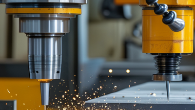
What Is One Off CNC Machining and How Does It Work?
one off cnc machining is the production of a single custom component using computer-controlled cutting equipment. Unlike mass production, it focuses on one prototype, replacement part, or highly specialized design. A digital CAD model guides the machine, while CAM software converts that model into controlled tool movements. The result may be an aluminum bracket, a steel shaft, or a small plastic enclosure.
The process begins with a technical drawing, material choice, and tolerance review. An experienced machinist checks wall thickness, tool access, hole depth, and surface requirements. These details matter. A design can look complete yet remain difficult to machine. The operator then selects cutting tools, secures the workpiece, and sets the machine coordinates. Milling, turning, drilling, or a combination of operations may follow.
Accuracy depends on more than software. Machine condition, fixture stability, material behavior, and operator judgment all influence the final part. After machining, technicians may measure critical features with calipers, micrometers, gauges, or a coordinate measuring machine. Inspection records can confirm whether the part matches the drawing.
One part is rarely effortless.
The approach can reduce tooling costs and support rapid design testing. However, it may cost more per unit than batch production. Complex geometry can also require multiple setups, increasing time and measurement risk. Even skilled teams must review unexpected results, such as tool wear or slight thermal movement. That reflection is valuable because practical machining often teaches something the original model did not show. Understanding how the process works helps engineers request realistic parts, communicate clearly, and make better manufacturing decisions.
Defining One-Off CNC Machining and Its Purpose
What Is One Off CNC Machining and How Does It Work?
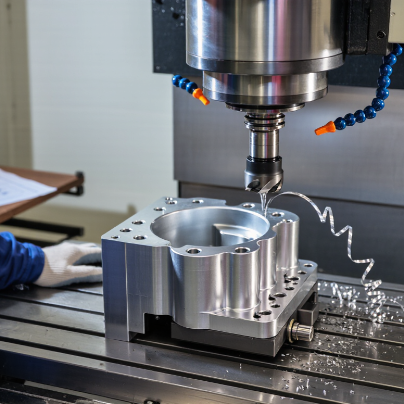
One-off CNC machining produces a single custom part or a very small quantity. Its purpose is practical: turning a specific digital design into a usable component without preparing for mass production. Engineers often choose this method for prototypes, replacement parts, test fixtures, or specialized equipment.
The process begins with a CAD model and a technical drawing. The drawing should identify material, dimensions, tolerances, surface finish, and critical features. CAM software then converts the design into cutting instructions. A machinist selects suitable tools, secures the material, sets work coordinates, and checks the first cuts carefully. Small details matter. A loose fixture can shift the part. A wrong datum can ruin accurate features.
One-off work demands more judgment than repetition. The machinist may adjust cutting speed after observing heat, vibration, or chip formation. Measurement tools verify key dimensions during and after machining. Deburring also deserves attention, especially around holes and sharp edges. The term “one-off” can be slightly misleading. It may describe one unique design, even when several test pieces are made. In practice, the first part often exposes weaknesses in the drawing or setup. That feedback can improve the next revision, although it may also reveal that the original tolerance was unnecessarily strict. Reliable results depend on clear documentation, controlled inspection, and honest communication about what the process can achieve.
Choosing Materials, Designs, and CNC Programming Requirements
What Is One Off CNC Machining and How Does It Work?
One-off CNC machining creates a single custom component from a digital design. It suits prototypes, replacement parts, and low-volume engineering tests. Material selection begins with the part’s real working conditions. Aluminum offers low weight and easy cutting. Stainless steel provides strength and corrosion resistance. Engineering plastics can reduce friction and electrical conductivity. However, material certificates and actual stock dimensions should be checked before machining.
Design decisions strongly affect cost and accuracy. Clear datum surfaces help the machine locate the part consistently. Practical wall thicknesses reduce vibration and distortion. Deep pockets may require longer tools, which can leave visible tool marks. Avoiding unnecessary tight tolerances is important. Keep features accessible.
The CNC programmer converts the CAD model into toolpaths and machine instructions. Workholding, cutting speeds, feed rates, and tool selection must match the chosen material. A simulation can reveal collisions, excessive tool reach, or missed surfaces. Yet simulation is not a substitute for judgment. In practice, the first setup is rarely perfect. A slightly shifting fixture or unexpected burr may require a revised operation. After cutting, critical dimensions should be inspected with calibrated instruments. Surface finish, hole position, and edge condition also deserve attention. Small details often decide whether a one-off part performs reliably.
Preparing the Machine, Tools, and Workholding Setup
One-off CNC machining begins long before the cutting tool touches metal. The operator studies the drawing, material, tolerances, and critical surfaces. A single part may justify extra setup time because mistakes cannot hide in a production batch. The machine table is cleaned carefully. Chips beneath a fixture can shift the workpiece by several hundredths of a millimeter. That small error may ruin a tight bore.
Tool preparation requires equal attention. Each cutter should match the programmed diameter, cutting length, and material requirements. Tool holders must be clean and seated firmly. The operator checks tool condition, measured length, and expected reach. A dull edge can produce heat, burrs, or a poor surface finish. It happens.
Workholding must resist cutting forces without distorting the part. Soft jaws can be machined to support irregular shapes, while parallels help maintain a repeatable height. The workpiece is positioned against reliable locating surfaces, then clamped evenly. Excessive pressure is a common mistake with thin sections. I have seen a secure-looking setup bend a part before machining even began.
After loading, the operator sets the work offset from a defined datum. A probe, edge finder, or carefully verified manual method can establish the location. The program is reviewed line by line for tool paths and clearance. A dry run above the material reveals unsafe movements. The first cut should be conservative. Measure the result with suitable instruments, compare it with the drawing, and adjust only after identifying the cause of any deviation.
What Is One Off CNC Machining and How Does It Work? - Preparing the Machine, Tools, and Workholding Setup
| Setup Area | Typical Preparation | Key Data or Selection Criteria | Verification Before Cutting | Purpose in One-Off Machining |
|---|---|---|---|---|
| 1. Review the part design | Study the CAD model, drawing, material specification, datums, hole locations, surface requirements, and critical dimensions. | Identify feature sizes, deep pockets, thin walls, internal corners, threads, chamfers, and required inspection points. | Confirm that the drawing revision, units, tolerances, and material callout are consistent. | A single part usually has limited opportunity for process correction, so design interpretation must be resolved before setup. |
| 2. Select raw stock | Choose bar, plate, billet, casting, or near-net stock with enough material for clamping and machining. | Allow machining stock on finished faces; account for saw-cut variation, flatness, distortion, and thermal expansion. | Check material certificate when required and verify the stock dimensions with calibrated measuring tools. | Correct stock size reduces unnecessary cutting time while preserving enough material to produce all finished features. |
| 3. Plan the machining sequence | Define the order for facing, roughing, drilling, pocketing, contouring, finishing, threading, deburring, and inspection. | Machine stable datums first; rough before finish; leave finishing stock where distortion or heat may affect accuracy. | Simulate toolpaths and check for collisions involving the tool, holder, spindle, workpiece, and fixture. | A logical sequence improves rigidity, maintains references, and minimizes the number of workholding changes. |
| 4. Prepare cutting tools | Select drills, end mills, face mills, ball-nose cutters, reamers, chamfer tools, thread mills, or taps as required by the part. | Match tool material, diameter, flute count, reach, corner radius, coating, and geometry to the workpiece material and feature. | Inspect edges for wear or damage; measure tool length and diameter; record tool offsets in the control. | Accurate tool data is essential when there is no production batch available to reveal setup errors gradually. |
| 5. Establish cutting conditions | Set spindle speed, feed rate, depth of cut, stepover, coolant method, and chip-control strategy. | Base settings on tool diameter, tool material, workpiece material, machine rigidity, engagement, and manufacturer cutting data. | Confirm that programmed speeds and feeds are within machine, holder, tool, and workpiece limits. | Balanced parameters help control heat, cutting force, tool deflection, surface finish, and tool life. |
| 6. Design the workholding setup | Select a vise, chuck, fixture plate, soft jaws, clamps, parallels, locating pins, or custom supports. | Provide positive location, adequate clamping force, tool clearance, chip evacuation, and support beneath thin or flexible areas. | Check that the workpiece cannot shift, lift, vibrate, or interfere with tool travel during the complete operation. | Rigid, repeatable workholding is necessary for dimensional accuracy and safe machining of a single custom part. |
| 7. Set work offsets | Locate the workpiece datum using an edge finder, probe, indicator, or accurately measured reference surface. | Define the programmed origin in X, Y, and Z; record separate offsets for additional setups when required. | Indicate key surfaces and compare measured locations with the drawing datums before running the program. | Correct work offsets connect the digital toolpath to the physical location of the part in the machine. |
| 8. Load and prove out the program | Transfer the CNC program, verify tool numbers and offsets, then perform a dry run, single-block check, or reduced-feed test. | Review rapid moves, work coordinates, spindle direction, coolant commands, tool changes, retract heights, and safety clearances. | Keep the feed override low during the first motion and stop immediately if position, sound, or chip formation is abnormal. | Program proving reduces the risk of scrapping the only part or damaging the machine and fixture. |
| 9. Machine and monitor | Run roughing and finishing operations while monitoring load, vibration, chips, coolant flow, temperature, and tool condition. | Watch for chatter, built-up edge, tool deflection, workpiece movement, burr formation, and unexpected dimension changes. | Pause for in-process measurements when a feature is critical or when tool wear may affect the final result. | Real-time observation allows corrective action before an isolated machining error becomes a finished-part failure. |
| 10. Inspect the finished part | Remove burrs carefully, clean the part, and inspect dimensions, geometry, threads, holes, surface finish, and visual defects. | Use micrometers, calipers, height gauges, bore gauges, indicators, thread gauges, or coordinate measurement equipment as appropriate. | Compare recorded results with drawing tolerances and retain inspection data for traceability when required. | Inspection confirms that the one-off component meets functional and dimensional requirements before release. |
| 11. Document the setup | Record the tool list, offsets, workholding arrangement, cutting parameters, inspection results, and changes made during machining. | Include setup photos, datum references, tool lengths, stock size, program revision, and notes about successful or unsuccessful operations. | Review the record for completeness and identify improvements if the part will be remade or modified later. | Although the job is one-off, documentation preserves useful process knowledge and makes future repeat work faster and safer. |
Note: Cutting parameters, achievable tolerances, and inspection methods must be selected for the specific machine, tool, workpiece material, geometry, and drawing requirements.
How the One-Off CNC Machining Process Is Carried Out
One-off CNC machining begins with a digital model, but the real work starts during preparation. The engineer checks material, tolerances, wall thickness, and tool access. A single prototype may use aluminum, steel, plastic, or titanium. The material choice changes cutting speed, coolant use, and finishing time.
The CAD file becomes CAM toolpaths, then machine code. The operator secures the raw billet and sets the work coordinate system. Probing verifies the stock position before cutting begins. Roughing removes bulk material with larger tools. Finishing tools then create the required surfaces and edges. Holes may require drilling, reaming, or tapping. A coordinate measuring machine can inspect critical dimensions after machining. ISO 230-2 testing also provides a recognized method for evaluating machine positioning accuracy. According to the U.S. Bureau of Labor Statistics, manufacturing still employs millions of workers, yet skilled technical labor remains difficult to replace. Human judgment matters here. Software does not always detect a weak setup.
Tips: Keep extra stock around critical surfaces. Confirm the datum twice. Measure the first feature before continuing. Industry reports from the International Federation of Robotics show continued automation growth, but one-off work still depends heavily on flexible operators. A perfect first setup is uncommon. Small errors in clamping can appear as large dimensional problems later. Record tool offsets, inspection results, and unexpected chatter. That record improves the next prototype, even when the first attempt feels inefficient.
Inspecting the Finished Part and Evaluating Its Benefits
What Is One Off CNC Machining and How Does It Work?
Inspecting the Finished Part and Evaluating Its Benefits
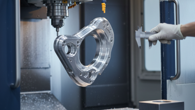
A one-off CNC part is not finished when the spindle stops. Inspection begins with cleaning away chips, coolant, and sharp burrs. The technician checks critical dimensions using calibrated calipers, micrometers, gauges, or a coordinate measuring machine. A bore may look correct but still fail its tolerance. That small difference can stop an assembly.
The inspection plan should follow the engineering drawing, including datum references, geometric tolerances, surface-finish requirements, and material specifications. NIST emphasizes traceable measurement through calibration and documented uncertainty. ISO 17025 also requires competent laboratories to control testing processes. For demanding parts, a dimensional report should record actual values, not only pass-or-fail results. Photographs can reveal tool marks, chatter, discoloration, or incomplete deburring. They are useful evidence. They are not measurement data.
The benefits of one-off machining become clearer after evaluation. There is little or no tooling investment, and design changes can move quickly into production. The finished part can validate fit before a larger batch begins. ASQ reports that poor quality may cost manufacturers 15% to 20% of sales, making early verification financially important. Still, one-off work is not automatically economical. Programming time, setup variation, and inspection effort can outweigh material savings. A perfect report can also hide a weak process if only one feature was tested. That is the uncomfortable part. The inspection method must be questioned, not merely completed.
What Is One-Off CNC Machining and How Does It Work?
Inspecting the Finished Part and Evaluating Its Benefits
One-off CNC machining produces a single custom component directly from a CAD model. After cutting, the finished part is inspected against the drawing for dimensional accuracy, surface condition, and critical features. The chart shows typical measurement resolutions for commonly used inspection equipment. Resolution indicates the smallest increment an instrument can display; actual measurement accuracy also depends on calibration, temperature, setup, and operator technique.
A caliper is suitable for general dimensions, while a micrometer provides finer readings for shafts, walls, and other precision features. A coordinate measuring machine can evaluate complex geometries and multiple datums with micrometre-level resolution. Inspecting the finished part helps verify the design before assembly, reduces the risk of rework, and provides fast feedback for design improvements in future iterations.
Related Posts
-
Top Benefits of One Off CNC Machining for Global Buyers?
-
2026 Best One Off CNC Machining Techniques for Precision
-
2025 How to Optimize CNC Machine Design for Maximum Efficiency and Performance
-
Top 10 One Off CNC Machining Benefits for Custom Manufacturing Success?
-

10 Essential Tips for Effective CNC Machine Design Strategies?
-

10 Essential Tips for Choosing the Right Machine Tool in CNC Production?
We Meet Our Clients Needs.
Meeting the diverse needs of our clients, we have complete machining facilities for everything from single part prototypes to large quantity production. Our small size is one of our biggest assets. It allows us to control costs and maintain the highest of standards.
Quality orientated and delivery always on time or earlier than originally promised.
Strongly recommend MSD.