
How to Choose a Three Phase RCBO in 2026?
Choosing a Three Phase Rcbo in 2026 is not simply a matter of matching voltage and current. The device must protect people, cables, motors, and equipment within a real installation. A workshop may have dust, long cable runs, frequent motor starts, and uneven loads. Each detail can affect tripping performance. Mike Holt, a respected electrical educator, says, “Safety is not expensive, it’s priceless.” That principle belongs at the center of every RCBO decision.
This guide explains how to compare rated current, breaking capacity, residual operating current, pole configuration, and trip characteristics. It also considers Type A, Type F, and Type B residual-current protection. Modern equipment can create pulsed or smooth DC leakage. A basic Type AC device may not provide suitable protection in every application. Always check the manufacturer’s technical data and the electrical design requirements. Local regulations and inspection practices still matter.
Small details matter.
A reliable selection also requires checking neutral switching, enclosure temperature, busbar compatibility, terminal capacity, and available fault current. Certification should be traceable, not merely printed on a sales page. Installation testing must confirm insulation resistance, polarity, loop impedance, and residual-current operation. However, product selection alone cannot guarantee safety. Incorrect wiring, poor torque, or skipped testing can defeat a high-quality Three Phase Rcbo. This is where experience becomes important. Even experienced designers can overlook harmonic currents or future load changes. That uncertainty deserves honest review before purchase.
What Is a Three-Phase RCBO and How Does It Work?
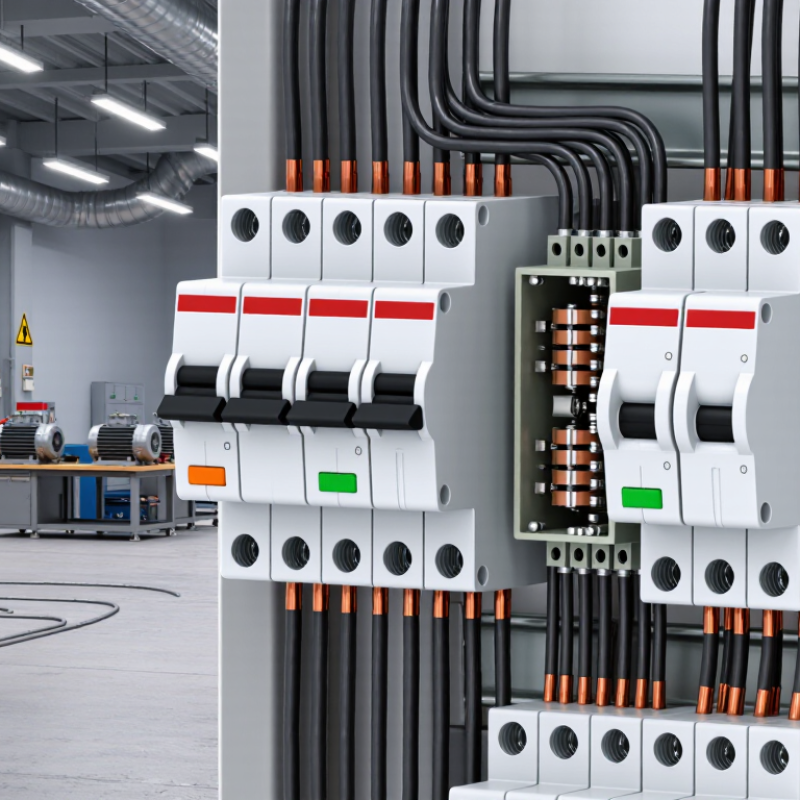
A three-phase RCBO combines residual current protection with overload and short-circuit protection. It is commonly used in three-phase distribution boards and industrial circuits. Unlike a single-phase device, it monitors three live conductors, and often the neutral conductor too. The RCBO checks whether the outgoing and returning currents remain balanced.
Under normal conditions, magnetic fields inside its sensing core cancel each other. If damaged insulation allows current to flow toward earth, the balance changes. The RCBO detects this residual current and trips quickly.
Its overcurrent section responds differently. A thermal element handles sustained overloads, while a magnetic element reacts to severe short circuits. Both functions operate inside one compact unit.
A suitable three-phase RCBO must match the system voltage, frequency, pole arrangement, rated current, and residual trip sensitivity. Confirm whether the circuit requires neutral switching. Check the prospective fault current against the device rating. During commissioning, press the test button and verify that every required pole disconnects. A test button is useful, but it does not prove every installation is safe.
In practice, cable size, load balance, earthing, and enclosure temperature affect performance. I would not select the device from current rating alone. That shortcut looks efficient, yet it can hide coordination problems. Manufacturer instructions and local electrical requirements still need careful review by a qualified professional.
Which Electrical Ratings Should a Three-Phase RCBO Have?
How to Choose a Three Phase RCBO in 2026?
Choosing a three-phase RCBO starts with the installation’s real electrical demand. Its rated voltage should match the system, commonly 400 V AC between phases. Check whether the circuit needs three poles or three poles plus neutral switching. The rated current must protect the cable, not merely match the connected equipment. A 32 A device may be unsuitable if cable size, ambient temperature, or installation method reduces capacity.
Breaking capacity is equally important. Select a rating above the prospective short-circuit current at the distribution board. Common values include 6 kA and 10 kA, but calculation is safer than guessing. The residual operating current, marked IΔn, needs careful thought. A 30 mA setting is widely used for additional personal protection. Higher settings may suit fire protection or selective coordination, where local rules permit them.
Do not overlook the RCD type. Type A detects AC and pulsating DC leakage, while Type F or Type B may suit equipment producing smoother DC components. The trip curve, such as B, C, or D, should reflect motor starting current without weakening fault protection. Frequency must also match the supply, usually 50 or 60 Hz. A tidy label does not prove correct selection. Verify the applicable standard, temperature derating, neutral arrangement, and coordination with upstream protection. One overlooked detail can affect the whole board.
How to Match Pole Configuration, Curve, and Trip Sensitivity
How to Choose a Three Phase RCBO in 2026?
Choosing a three phase RCBO starts with the circuit arrangement. A three-pole device protects three live conductors. A four-pole model also switches the neutral conductor. Use four poles when the installation design requires complete isolation, especially in systems with a shared or sensitive neutral. Never assume the neutral can remain connected. Verify the supply system, earthing method, and local electrical requirements with a qualified professional.
The curve must match the connected load, not just the breaker rating. Curve B suits circuits with low starting currents, such as lighting and resistive heating. Curve C tolerates moderate inrush from pumps, compressors, and small motors. Curve D is intended for higher starting currents, but it can require careful fault-current verification. A wrong curve may trip during startup or reduce protection quality.
Trip sensitivity needs equal attention. A 30 mA residual-current setting is commonly selected for additional protection against electric shock. Higher settings, such as 100 mA or 300 mA, may suit equipment protection or fire-risk control, depending on the installation design. Select the residual-current type for the load, too. Variable-speed drives and electronic equipment can produce complex leakage currents. Type A may be more suitable than Type AC in many modern circuits, but this is not universal. Check the equipment instructions and coordination requirements. A tidy specification can still be wrong. Real measurements matter.
How to Choose a Three Phase RCBO in 2026? - How to Match Pole Configuration, Curve, and Trip Sensitivity
| Selection Dimension | Available Option | Typical Technical Meaning | Recommended Use | Important Matching Check |
|---|---|---|---|---|
| Pole configuration | 3P | Three phase conductors are protected and switched; the neutral is not switched by the device. | Balanced three-phase loads that do not require a switched neutral, subject to local wiring rules. | Confirm that the circuit does not use a neutral conductor and that the device is approved for the intended system. |
| Pole configuration | 3P+N / 4P | Three phase conductors and the neutral pass through the RCBO; the protective mechanism normally disconnects all relevant conductors together. | Three-phase, four-wire circuits with line-to-neutral loads, mixed loads, or installations where neutral isolation is required. | Use a compatible neutral connection and verify whether the selected device switches or only monitors the neutral. |
| System arrangement | 400/230 V, three-phase, four-wire system | Approximately 400 V phase-to-phase and 230 V phase-to-neutral in commonly used IEC systems. | Commercial, industrial, and residential distribution with both three-phase and single-phase loads. | Check the RCBO voltage rating, frequency, neutral arrangement, earthing system, and installation standard. |
| Overcurrent curve | B curve | Magnetic instantaneous operation typically occurs at approximately 3–5 times the rated current (In), according to IEC miniature circuit-breaker conventions. | Low-inrush lighting, resistive loads, and general circuits with limited motor or transformer starting current. | Verify that normal starting current will not cause unwanted instantaneous trips. |
| Overcurrent curve | C curve | Magnetic instantaneous operation typically occurs at approximately 5–10 times In. | General commercial and industrial circuits, small motors, pumps, fans, contactors, and moderate inrush loads. | Usually the practical starting point for mixed three-phase loads, provided cable protection and fault-loop conditions are suitable. |
| Overcurrent curve | D curve | Magnetic instantaneous operation typically occurs at approximately 10–20 times In. | High-inrush motors, transformers, compressors, and specialist equipment with documented starting-current requirements. | Do not select D merely to prevent nuisance tripping; confirm disconnection time and available short-circuit current. |
| Residual-current type | Type AC | Detects sinusoidal alternating residual current. | Only fixed loads known to produce sinusoidal AC leakage, where permitted by local regulations. | Avoid for equipment likely to generate pulsating DC or smooth DC residual current. |
| Residual-current type | Type A | Detects AC and pulsating DC residual current. | Modern electronic loads, rectifiers, LED drivers, appliances, variable-speed equipment, and general commercial circuits. | A common default for modern installations, but confirm the equipment manufacturer's requirements. |
| Residual-current type | Type F | Designed for specified mixed-frequency residual currents and equipment with single-phase variable-speed drives. | Certain inverter-driven appliances, heat pumps, air-conditioning units, and similar loads when required by the equipment documentation. | Check the product standard and permitted frequency range before use. |
| Residual-current type | Type B | Detects AC, pulsating DC, and smooth DC residual current within its specified operating range. | Three-phase drives, photovoltaic inverters, battery systems, electric-vehicle charging equipment, and other loads that may produce smooth DC leakage. | Use only where system design or equipment instructions require it; confirm compatibility and DC detection limits. |
| Trip sensitivity, IΔn | 10 mA | Very high residual-current sensitivity for additional protection in selected applications. | Special locations or individual final circuits where a risk assessment and local rules justify increased sensitivity. | May be more vulnerable to nuisance tripping from accumulated normal leakage. |
| Trip sensitivity, IΔn | 30 mA | Common additional-protection threshold for personnel protection on final circuits, where required. | Socket outlets, portable equipment, wet-area circuits, and many general final circuits subject to local regulations. | The total standing leakage downstream should remain low enough to avoid nuisance operation. |
| Trip sensitivity, IΔn | 100 mA | Higher residual-current threshold, generally used for equipment or fire-risk protection rather than direct personal protection. | Selected upstream or dedicated circuits where a 30 mA device is unsuitable and regulations permit. | Do not treat 100 mA as an automatic substitute for 30 mA additional protection. |
| Trip sensitivity, IΔn | 300 mA | Higher threshold commonly associated with upstream equipment or fire protection strategies. | Main distribution or large fixed equipment when required by the protection study and local code. | Normally requires coordination with downstream 30 mA protection. |
| Selectivity | Standard, non-selective RCBO | Trips without a guaranteed time delay for coordination with an upstream residual-current device. | Individual final circuits where only local fault isolation is required. | Check the complete protection chain if an upstream RCD or RCBO is installed. |
| Selectivity | Time-delayed / selective type | Provides a specified delay to improve discrimination with downstream residual-current protection. | Upstream distribution protection in coordinated multi-level systems. | Use only when the product marking, tested combinations, and local installation rules support selectivity. |
| Rated current, In | Selected from the standard rating range | The continuous current rating of the RCBO, commonly selected from values such as 6 A, 10 A, 16 A, 20 A, 25 A, 32 A, 40 A, 50 A, or 63 A, subject to product availability. | Any three-phase circuit after calculating design current and load diversity. | Choose In no higher than the permitted current-carrying capacity of the conductors after derating. |
| Short-circuit capacity | Rated short-circuit capacity, Icn/Icu as applicable | The maximum prospective fault current that the device can safely interrupt under its applicable product standard. | All installations, especially circuits close to transformers or high-capacity distribution boards. | The device rating must be equal to or greater than the calculated prospective short-circuit current at the installation point. |
How to Check Installation Standards and System Compatibility
How to Choose a Three Phase RCBO in 2026?
A three-phase RCBO should match the installation standard used in your country. Check the latest national rules, not only a product datasheet. IEC 61009-1 is a useful reference for many low-voltage RCBO applications, but local requirements may add stricter conditions.
Confirm the rated voltage, frequency, breaking capacity, and number of protected poles. A four-pole device may be necessary when the neutral must disconnect with the phases. That detail is easy to underestimate.
System compatibility requires a close inspection of the distribution board. Check the DIN-rail space, busbar arrangement, terminal size, and neutral layout before ordering. The RCBO must suit the cable cross-section and the circuit’s expected load.
Select the residual-current type according to the equipment. Type A can detect pulsating DC leakage from many modern electronic loads, while other equipment may require a different response. A 30 mA setting is common for personal protection, but it must follow the local design requirements.
Installation quality matters as much as selection.
A qualified electrician should verify phase identification, torque settings, insulation resistance, polarity, and earth continuity. Test the RCBO with suitable equipment after energising the circuit. The test button is useful, but it does not replace a proper instrument test.
I once underestimated how easily a crowded enclosure can hide a loose neutral connection. That mistake changed my inspection routine.
Leave clear access, record the test results, and review the complete circuit rather than trusting one component.
How to Compare Safety Features, Quality, and Long-Term Value
How to Choose a Three Phase RCBO in 2026?
How to Compare Safety Features, Quality, and Long-Term Value
A three-phase RCBO should match the circuit, not just the panel space. Check its rated current, voltage, pole configuration, short-circuit capacity, and trip curve. IEC 61009-1 covers household and similar RCBO requirements, while IEC 62423 addresses additional residual-current types. Type A protection suits many modern loads with electronic controls. Type B may be necessary for equipment producing smooth DC leakage, such as some drives or charging systems. Selection depends on measured load behavior.
Safety margins matter. NFPA’s Home Fires Involving Electrical Distribution and Lighting Equipment report recorded approximately 32,000 U.S. home fires annually from 2016–2020. Those incidents caused hundreds of deaths and more than one billion dollars in property damage each year. An RCBO cannot prevent every fire. However, correct residual-current protection can reduce shock and leakage risks when installed and tested properly. Look for clear test-button operation, secure terminals, reliable neutral switching, and independent conformity assessment. Cheap plastic tells little.
Long-term value includes stable operation after heat, vibration, and repeated trips. Compare temperature derating, terminal torque guidance, mechanical endurance, spare availability, and documented test results. A useful inspection record should show trip times and leakage readings, not merely a tick. The lowest price may be sensible in a small, lightly loaded circuit. It may be false economy in a busy three-phase installation. I would still verify the actual fault level and leakage profile before choosing.
Labels are not measurements.
Article Source:
We Meet Our Clients Needs.
Meeting the diverse needs of our clients, we have complete machining facilities for everything from single part prototypes to large quantity production. Our small size is one of our biggest assets. It allows us to control costs and maintain the highest of standards.
Quality orientated and delivery always on time or earlier than originally promised.
Strongly recommend MSD.