
What Is an Anchor Flange Pipeline and How Does It Work?
An Anchor Flange Pipeline is more than a steel pipe with a welded collar. It is a controlled restraint system. The anchor flange transfers axial forces into concrete, piles, or a structural frame. It helps manage pressure thrust, thermal movement, vibration, and installation loads at critical pipeline points.
The need is substantial. The American Society of Civil Engineers’ 2021 Infrastructure Report Card rated U.S. drinking water infrastructure C−, highlighting aging assets and increasing renewal demands. AWWA’s State of the Water Industry reports also identify asset management, workforce capability, and resilient infrastructure as persistent industry priorities. These findings matter because a pipeline joint can look secure while its surrounding support quietly weakens. Small movements can become expensive failures.
Designers typically review operating pressure, pipe diameter, temperature change, soil stiffness, support spacing, and concrete capacity. ASME B31.4 and B31.8 provide widely used pipeline design frameworks, while AWWA standards support water-system engineering and installation practices. However, no single standard automatically defines every anchor arrangement. Project conditions decide the details.
The mechanism is practical. Internal pressure creates thrust at bends, reducers, valves, and closed ends. Thermal expansion adds another force. The anchor flange captures these loads and directs them into a designed restraint zone. Weld quality, flange geometry, corrosion protection, and concrete reinforcement all matter.
The overlooked part is installation.
Poor alignment can preload the system. Inadequate curing can reduce restraint capacity. Engineers should verify calculations, inspection records, and field conditions before commissioning. An Anchor Flange Pipeline can be highly reliable, but only when its surrounding structure is treated as part of the pipeline—not as an afterthought.
What Is an Anchor Flange Pipeline?
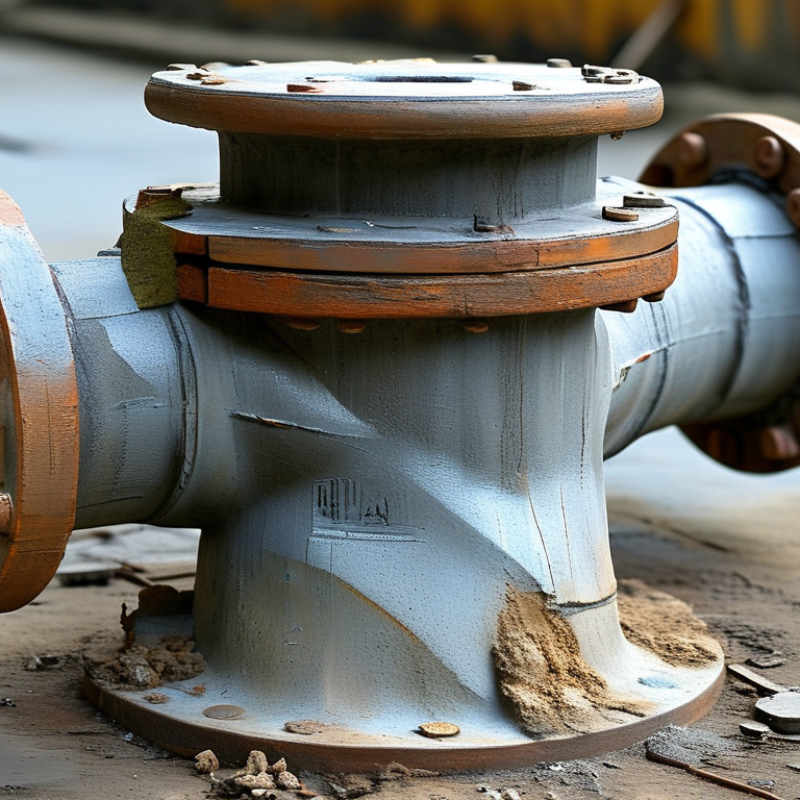
An anchor flange pipeline is a pipe assembly designed to control movement and hold a line at a fixed location. The anchor flange connects to a reinforced support, wall, or concrete structure. It transfers axial thrust from internal pressure, valves, bends, and thermal expansion into that support. Unlike a standard flange, it is not used only for joining pipes. Its main purpose is restraint. Engineers select it according to pipe size, pressure rating, temperature, material, and expected loads. Weld quality and local stresses also require careful checking.
When fluid pressure enters the pipeline, it creates force along the pipe axis. The anchor flange resists this force through bolts, welds, and its supporting structure. At a bend, pressure can create unbalanced thrust. The anchored section limits movement and protects nearby joints. Thermal changes still cause expansion elsewhere, so guides and expansion allowances remain important. Field reviews often reveal that support capacity was assumed, not verified. That weakness can remain hidden until operation begins. Alignment, bolt tightening, weld condition, and concrete strength should be checked before commissioning.
Tips: Keep the anchor point near major directional changes when calculations support it. Do not treat every flange as an anchor. Review load paths with a qualified pipeline engineer. Check corrosion protection near buried transitions. Small alignment errors can become serious leaks.
What Is an Anchor Flange Pipeline and How Does It Work?
| Data Dimension | Technical Description | How It Works or Why It Matters |
|---|---|---|
| Definition | A pipeline system that incorporates one or more anchor flanges to control axial movement and transfer pipeline forces to a supporting structure. | The anchor flange creates a fixed restraint point, allowing the remaining pipe sections to expand, contract, or move in a controlled manner. |
| Primary Function | Resist axial thrust, thermal expansion forces, pressure-induced end loads, and selected mechanical loads. | It prevents unwanted pipe displacement and helps protect joints, valves, bends, equipment connections, and supports. |
| Main Components | Pipe barrel, anchor flange or welded collar, connecting flanges, bolts, gaskets, supports, and a concrete or structural anchoring system. | The flange transfers force from the pipe wall into the surrounding support through its connection and bearing surfaces. |
| Typical Anchor Location | Near a change in direction, a valve chamber, a fixed equipment connection, a pipe end, or another location where axial restraint is required. | These locations commonly generate or receive unbalanced forces that must be transferred safely to a foundation or structural frame. |
| Pressure Thrust | For a closed pipe end, pressure thrust can be estimated as F = P × A, where P is internal pressure and A is the effective internal area. | The resulting force must be included when sizing the flange, bolts, welds, supports, and foundation. |
| Thermal Movement | Pipe length changes as temperature varies; the approximate free expansion is ΔL = α × L × ΔT. | Anchors limit movement at selected points while expansion joints, loops, guides, or sliding supports manage movement elsewhere. |
| Load Transfer Path | Internal pressure and pipe movement create axial forces that pass through the pipe wall, anchor flange, bolts or welds, support structure, and foundation. | A continuous load path is essential; weak connections or inadequate foundations can cause movement, leakage, or structural damage. |
| Common Materials | Carbon steel, stainless steel, ductile iron, and other materials selected according to fluid compatibility, pressure, temperature, corrosion conditions, and design codes. | Material selection affects strength, corrosion resistance, weldability, gasket compatibility, and service life. |
| Applications | Water transmission, wastewater systems, industrial process piping, cooling-water lines, fire-protection networks, and buried or above-ground pressure pipelines. | Anchor points are used wherever pressure forces, thermal effects, or directional changes could cause unacceptable pipe movement. |
| Difference from a Standard Flange | A standard flange primarily provides a detachable connection or joining surface, while an anchor flange is specifically designed to provide axial restraint. | Not every flanged joint is an anchor point; restraint requires suitable structural attachment and engineering verification. |
| Design Checks | Pressure thrust, thermal loads, bending moments, seismic or vibration loads, bolt and weld capacity, bearing stresses, fatigue, corrosion, and foundation stability. | The complete system—not only the flange—must be checked so that the restraint does not transfer excessive loads to adjacent components. |
| Installation Considerations | Confirm alignment, weld quality, bolt tightening, gasket installation, coating or corrosion protection, concrete reinforcement, and access for inspection. | Correct installation ensures that the intended forces are transferred without leakage, distortion, or premature deterioration. |
| Key Benefit | Improved control of pipeline movement and reduced risk of damage at fittings, joints, supports, and connected equipment. | A properly designed anchor flange pipeline improves system stability, service reliability, and maintenance performance. |
We Meet Our Clients Needs.
Meeting the diverse needs of our clients, we have complete machining facilities for everything from single part prototypes to large quantity production. Our small size is one of our biggest assets. It allows us to control costs and maintain the highest of standards.
Quality orientated and delivery always on time or earlier than originally promised.
Strongly recommend MSD.